

A salad dressing closure is acceptable only when it stays attached, maintains a continuous seal and dispenses the formula without creating an opening problem for the consumer. Those results depend on the bottle finish, cap shell, liner or plug seal, dispensing feature, application process and dressing formula working together. A cap that passes on an empty reference bottle can still leak after oil reaches the sealing land, after the threads relax or after a filled case experiences warm transit.
Qualification should therefore use production-representative bottles and closures filled with the actual dressing or a justified worst-case formula. Threaded closures need engagement, application torque, removal torque and strip-margin evidence. Snap-on closures need seating-force, retention-force and bead-engagement evidence. Both routes need conditioned leak testing, sealing-surface inspection and repeated dispensing checks.
The most useful release document is not a generic certificate that says the cap fits. It is a component-specific operating window that states the approved bottle and closure drawings, application settings, conditioning sequence, test methods and pass criteria.
| Validation Question | Primary Evidence | Failure Prevented |
|---|---|---|
| Is the attachment geometry compatible? | Finish drawing, closure drawing, molded-part dimensions and assembly section | Cross-threading, incomplete snap engagement and closure lift |
| Can production apply the closure consistently? | Application torque or push-on force window with line samples | Cocked caps, stripped threads and partially seated snap-ons |
| Does the seal remain continuous? | Sealing-land inspection, liner or plug contact and conditioned leak tests | Oil tracks, side-lay leakage and oxygen ingress |
| Can consumers open and use the package? | Immediate and aged removal torque, lid opening force and dispensing checks | Hard opening, loose caps and inconsistent serving |
Choose the Attachment System Before Writing the Test Plan
Continuous-thread closures are installed by rotation. Their performance depends on thread start alignment, pitch compatibility, thread overlap, vertical travel, top load and the way the liner or plug reaches the bottle sealing surface. Disc-top and flip-top dispensing features may be built into the threaded closure, but the lid function does not replace the need to validate the cap-to-bottle attachment.
Snap-on closures are pressed over a retention bead or locking feature. Their critical events are alignment, bead expansion, full seating and elastic recovery behind the bead. A cap can look level while only part of the circumference is engaged, so visual inspection should be paired with force-displacement data or a sectioned assembly.
Nominal descriptions such as 38-400 and 38-485 help organize components, but they are not approval by themselves. The nominal diameter and finish-series designation do not prove that thread profiles, seal geometry, tamper features or dispensing clearances match. Use the controlled drawings and production samples for the exact bottle and closure.
| Attachment Route | Control During Assembly | Critical Release Measurements |
|---|---|---|
| Continuous thread | Cap alignment, application torque, top load and chuck condition | Thread engagement, immediate and aged removal torque, strip torque and seal contact |
| Snap-on | Cap orientation, push-on stroke, seating force and support under the finish | Seating signature, final height, circumferential engagement and pull-off retention |
| Threaded dispensing cap | Thread application plus disc-top or flip-top lid function | Attachment torque, land seal, lid opening force, orifice behavior and leakage |
| Snap-on dispensing cap | Retention-bead engagement plus lid or valve assembly | Push-on force, pull-off force, dispensing performance and cap-down leakage |
Verify Thread Engagement From Drawings and Molded Parts
Start with the bottle-finish and closure drawings. Compare thread starts, pitch, lead, major and minor diameters, thread height, closure skirt depth, vertical clearance and the location of the sealing system. The cap must reach its sealing position before the thread runs out of travel, and the thread must retain enough overlap to resist handling and removal without approaching its strip limit during normal application.
Measure molded parts rather than approving nominal dimensions alone. Neck ovality, flash, sink, gate distortion and cap shrinkage can change fit even when the drawing pair is correct. Use appropriate gauges, a profile projector, optical measurement or sectioning to confirm the actual engagement. Sample more than one bottle cavity and closure cavity because a single favorable pair can hide a tolerance-stack problem.

Inspect applied caps for cocking, thread shaving, stress whitening and uneven skirt height. A destructive vertical section can show whether the threads share load across the intended area and whether the liner, land seal or plug is centered. Record the cavity and lot identifiers with every section so a localized mold condition can be traced.
Measure Snap-On Seating and Pull-Off Retention
A snap-on closure should produce a repeatable force-displacement signature as the skirt expands over the bottle bead and then seats below it. Record peak seating force, final closure height and any force drop associated with full engagement. An unusually low peak can indicate an undersized bead, an oversized closure or incomplete measurement support. An unusually high peak can deform the finish, damage the cap or overload the assembly equipment.
Retention is measured by pulling the applied closure in a controlled fixture while recording force and displacement. The fixture must load the closure evenly; a tilted pull can measure one local weak point instead of circumferential retention. Note whether failure occurs by closure release, skirt tearing, bead damage or bottle-finish deformation because the same peak force can represent very different package risks.
Condition retention samples before release. Oil, acid, warm storage and material relaxation can change the force after assembly. Test the agreed initial point and aged points, then compare them with filled-package leakage and opening behavior. The acceptance limit belongs to the approved bottle-cap system and use case; it should not be copied from an unrelated package.
Set Application and Removal Torque for Threaded Closures
Application torque must be high enough to establish the designed seal but low enough to preserve thread integrity and consumer access. Build the operating window from the actual bottle, cap, liner and capping equipment. Record immediate removal torque after a defined dwell, then repeat after storage and thermal conditioning to quantify relaxation or any increase caused by liner compression, product exposure or finish movement.
Use a calibrated digital torque tester or an automated system with a fixture that holds the bottle without distorting it. Keep the test direction, speed, dwell time and conditioning consistent. ASTM D2063/D2063M provides a recognized framework for torque retention of continuous-thread closures, but the project specification still needs its own sampling plan and acceptance values.
Measure strip torque separately from normal removal torque. The production application setting needs a documented margin below the level where threads override, the closure deforms or the finish is damaged. Also inspect for cap back-off, cocking and liner rotation; a torque number can look acceptable while the seal is uneven.
| Torque Result | What It Describes | Common Diagnostic Use |
|---|---|---|
| Application torque | Rotational input from the capper | Controls initial seating and identifies head-to-head variation |
| Immediate removal torque | Opening torque after a defined short dwell | Confirms initial retention and detects gross under- or over-application |
| Aged removal torque | Opening torque after specified storage or conditioning | Shows relaxation, liner set, product exposure and consumer-opening risk |
| Strip torque | Torque at thread override or structural damage | Defines the upper mechanical margin for the approved components |
Protect the Sealing Land From Dressing Contamination
Many apparent cap failures begin before the cap is applied. Dressing splashed onto the bottle land or threads can interrupt liner contact, reduce plug-seal friction or create a capillary leak path. Oil-rich vinaigrettes are especially useful as challenge products because a thin oil track can travel through a small discontinuity that a thick dressing temporarily masks.
Inspect the finish immediately before capping and again after failed leak tests. The sealing land should be free of flash, nicks, contamination and excessive ovality. For a linered closure, confirm that the liner covers the required surface without wrinkling, folding or rotating. For a linerless plug or land seal, confirm insertion depth, concentricity and contact around the full circumference.
Separate dispensing leakage from attachment leakage. Product on the disc-top or flip-top orifice may come from incomplete lid closure, residue or a damaged dispensing seal. Product below the cap skirt may come from the bottle land, liner, plug or thread path. Marking and photographing the first visible leak location makes corrective action faster.
Run Leak Tests That Reproduce Distribution and Use
Begin with filled bottles using the intended headspace, application setting and closure assembly. Include upright, side-lay and inverted orientations where they reflect case packing, e-commerce handling or consumer storage. Condition samples at relevant refrigerated, ambient and warm temperatures, then inspect at defined intervals for wetting, oil tracks, drops, cap movement and label or carton damage.
A vacuum chamber can expose leakage under a pressure differential, but the result depends on product viscosity, headspace, chamber profile and observation method. ASTM D5094/D5094M describes gross leakage testing for threaded or lug closures on containers. Use it as a method reference, then define the package-specific vacuum level, dwell, orientation and pass rule. A continuous bubble stream or product track should be traced to its actual seal path rather than reported only as a failed bottle.
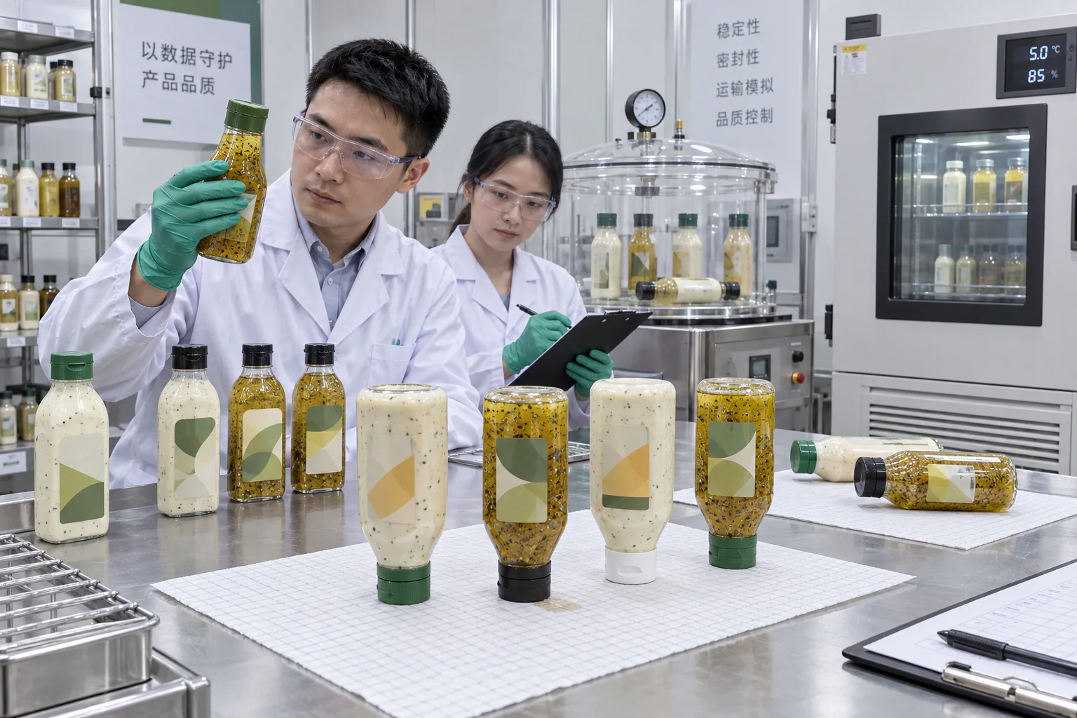
Follow conditioning with realistic handling. Vibration, drops and case compression can loosen an attachment or move dressing onto the sealing surface. Retest removal torque, cap height and leakage after distribution simulation. For dispensing closures, cycle the lid and orifice with the actual dressing, wipe only as instructed in the consumer-use protocol and repeat side-lay or cap-down storage.
Known-good controls and intentional leak controls help confirm that the equipment and observer can distinguish a sealed package from the defect level the protocol is intended to detect. Without controls, a quiet chamber can be mistaken for proof of a robust seal.
Separate Attachment, Seal, and Dispensing Failures
When a package leaks, preserve it in the failed orientation before disassembly. Photograph the lid, orifice, cap skirt, thread area and bottle shoulder. Mark the first wet location, record the conditioning history and keep the bottle, closure, liner and dressing batch together. Wiping or tightening the cap before inspection destroys evidence.
An attachment failure includes cross-threading, cap back-off, partial snap engagement or low pull-off retention. A seal failure occurs when product crosses the liner, plug or bottle-land interface while the attachment remains in place. A dispensing failure occurs at the disc-top, flip-top, valve or orifice. The corrective action differs: changing capper torque will not repair a warped sealing land, and a tighter cap will not correct a contaminated dispensing lid.
Use a structured fault tree. Compare the failed sample with dry controls, filled controls and components from other cavities or lots. Check whether the issue follows the bottle, the closure, the liner, the formula or the application station. This prevents unnecessary tooling changes and makes supplier corrective action specific.
| Observed Evidence | Likely Failure Family | Next Check |
|---|---|---|
| Uneven skirt height or shaved thread | Thread engagement or capper alignment | Finish dimensions, cap dimensions, thread start and chuck alignment |
| Snap cap releases without skirt damage | Insufficient bead engagement or relaxation | Bead geometry, seating signature, conditioned pull-off force |
| Oil track below an intact cap | Land, liner or plug-seal discontinuity | Finish cleanliness, flatness, liner coverage and seal contact |
| Product only on the dispensing face | Lid, orifice or residue-control problem | Lid closure force, plug feature, wiping protocol and repeated cycles |
Build OQ and PQ Sampling Around Real Variation
Operational qualification should challenge the intended application window, not only the nominal machine setting. For threaded closures, include the planned low, center and high application settings plus relevant line speeds and capping heads. For snap-ons, include seating-stroke or force limits and support conditions. Verify that every challenged setting still produces acceptable attachment, seal and opening results.
Performance qualification should use production materials and normal operators across representative runs. Sample bottle and closure cavities, start-up and steady-state production, multiple capper heads and the intended dressing batch range. Retain labeled components and filled packages so a delayed market or shelf-life observation can be traced.
Write sample size and acceptance criteria from risk, process capability and customer requirements. Critical leakage and detached-closure failures normally require stringent disposition, while dimensional and torque data can also be trended for drift. Do not hide a critical failure inside an average.
- Record bottle, closure, liner and dressing lot numbers for every test group.
- Identify molding cavities and capping heads whenever the process allows.
- Use the same conditioning time before comparing removal-torque results.
- Retain failed assemblies without cleaning or retightening them.
- Link any process adjustment to a repeat of the affected seal and use tests.
How Gracepack Supports Closure-System Qualification
Gracepack can coordinate the bottle, cap, liner or valve and application review as one packaging system. A technical sample route can start with the dressing type, oil content, pH if available, viscosity, particles, fill temperature, bottle capacity, storage orientation and target market, then narrow the attachment and dispensing options before artwork or mass production.
For PET, PP, PE and silicone component routes, food-contact documentation is matched to the actual component set instead of being represented by a generic bottle statement. The quality route can also preserve approved samples, component lots and agreed dimensions so repeat orders are compared with the released package.
Factory trials can cover finish measurement, cap fit, torque or retention, filled-package leakage and dispensing checks. The result is a practical approval pack for the selected clear salad dressing bottles, disc-top dressing caps or flip-top caps, with the production settings and failure definitions carried into the purchase specification.
Release Checklist for Salad Dressing Closure Systems
Release the package only when the evidence covers the complete commercial configuration. A closure drawing and a dry fit are useful inputs, but they do not replace filled-package validation with the intended formula, line settings and distribution conditions.
- Approve the exact bottle, closure, liner or valve drawings and material specifications.
- Confirm molded finish, sealing-land and closure dimensions across representative cavities.
- Verify thread engagement or snap-bead seating on production-representative assemblies.
- Establish application settings, immediate results, aged results and mechanical margins.
- Inspect sealing surfaces before capping and after every failed leak test.
- Run upright, side-lay or inverted leakage conditions that match the route to market.
- Repeat seal and opening checks after distribution and temperature conditioning.
- Define failure categories for attachment, land seal, liner, plug and dispensing feature.
- Keep traceable approved samples and retain failed packages without cleaning them.
FAQ About Salad Dressing Bottle Closure Validation
Does a 38 mm cap automatically fit every 38 mm bottle?
No. The nominal diameter does not prove thread-series, seal, skirt-depth or tamper-feature compatibility. Approve the exact drawings and molded components.
What is the difference between application torque and removal torque?
Application torque is applied by the capper. Removal torque is measured when opening the package after a defined dwell or conditioning period. They answer different process and use questions.
How is a snap-on closure validated?
Record its push-on force and seating signature, confirm circumferential bead engagement, measure conditioned pull-off retention and complete filled-package leak testing.
Should leak testing use water or the actual dressing?
Water can commission equipment, but release testing should use the actual dressing or a justified worst case because oil, acid, viscosity and particles change wetting and leakage behavior.
Why should torque be checked after storage?
Plastic and liner materials relax, temperatures change and the product can affect interfaces. A cap that opens correctly immediately after application may be too loose or too difficult after conditioning.
What information is needed for a closure fit review?
Provide the bottle and cap drawings or samples, dressing type, oil content, pH if available, viscosity, particles, fill process, storage orientation, case configuration, destination market and current failure symptoms.


