
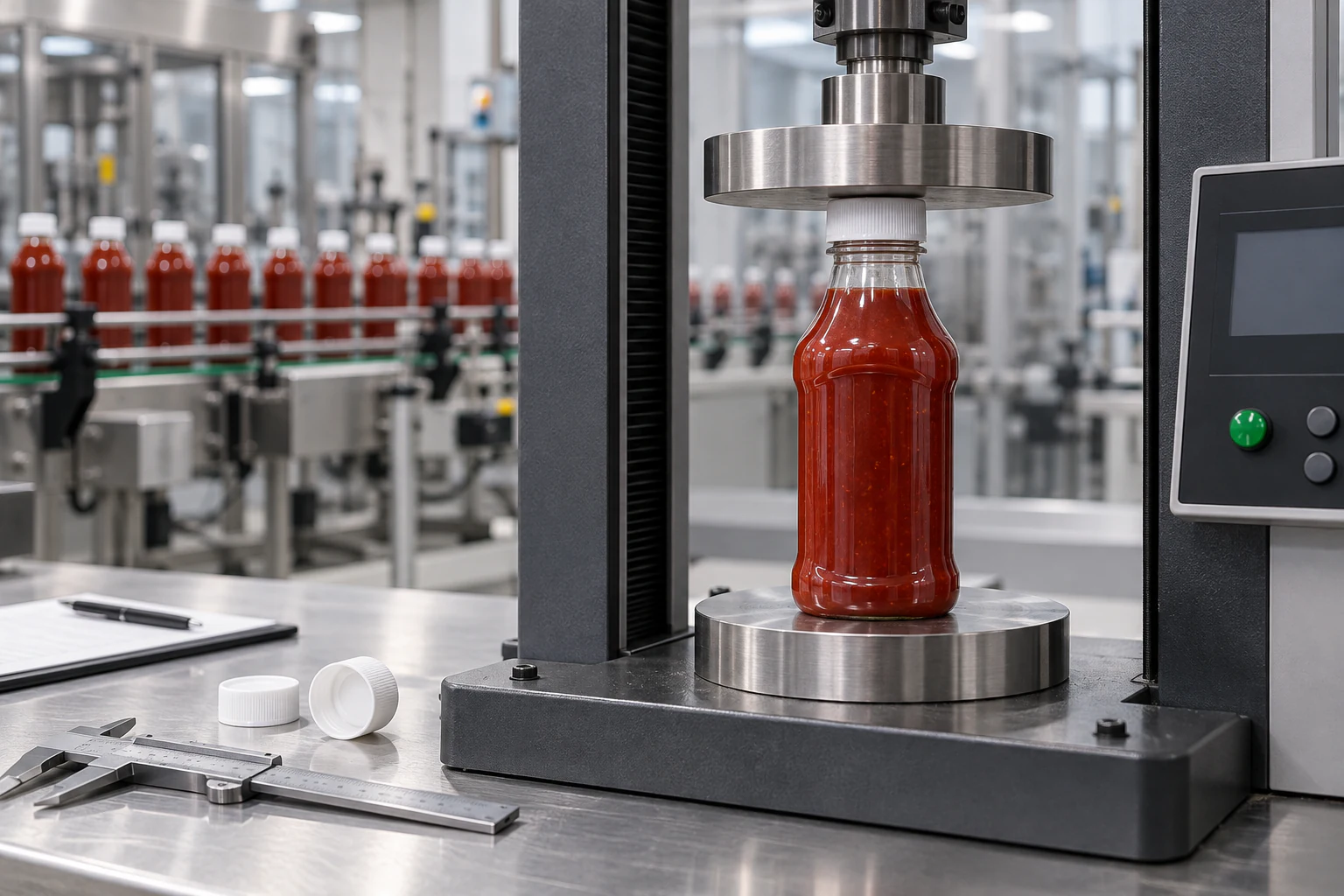
Top-load testing compresses a sauce bottle axially at a controlled rate and records force against displacement. For capping-line qualification, the useful result is not one headline crush force: it is the load at first structural yield, neck movement at the capper's working load, wall-buckling location, permanent height loss and the difference between room-temperature and process-conditioned bottles.
There is no universal pass value for every PET, HDPE or PP sauce bottle. The acceptance window must be tied to the actual bottle geometry, resin, gram weight, cap, fill condition, test speed and measured capper downforce. A bottle can post a high final crush load yet fail the line earlier because the neck tilts enough to cross-thread a cap or the shoulder loses height before the recorded peak.
| Top-Load Result | What It Measures | Why It Matters at the Capper |
|---|---|---|
| Force at specified displacement | Load carried before an allowed amount of shortening | Shows whether the bottle remains dimensionally usable under working downforce |
| Deflection at specified force | Bottle height change at a defined process load | Reveals neck drop or shoulder movement before visible collapse |
| First yield or first peak | First irreversible structural event on the force-displacement curve | Often corresponds to neck deflection, shoulder snap-through or local wall buckling |
| Maximum force | Highest axial force reached in the selected test window | Useful for design comparison, but insufficient as the only line-acceptance criterion |
| Apparent stiffness | Slope of the curve over a defined elastic region | Detects soft lots or cavities before catastrophic failure occurs |
| Permanent set | Residual height or shape change after unloading | Identifies bottles that look intact but no longer present the finish correctly to the capper |
Build a Repeatable Sauce Bottle Top-Load Test Method
Start by defining the exact test article. Empty uncapped bottles isolate the molded container, while capped or filled bottles introduce headspace, product support, closure compression and internal pressure. Results from those configurations cannot be pooled. Record resin, bottle weight, mold cavity, production time, finish, cap, fill mass, headspace, bottle temperature and conditioning time for every group.
Place the bottle upright between parallel platens and center the finish beneath the load axis. A tilted platen can create the same asymmetric neck failure that the test is supposed to diagnose. Set one crosshead speed and stop rule for the specification, then keep them unchanged across approval and production lots. ASTM D2659 provides a standardized framework for column-crush properties of blown thermoplastic containers, including crushing yield load, deflection at yield, failure load and apparent stiffness, but results are meaningful only under comparable test conditions.
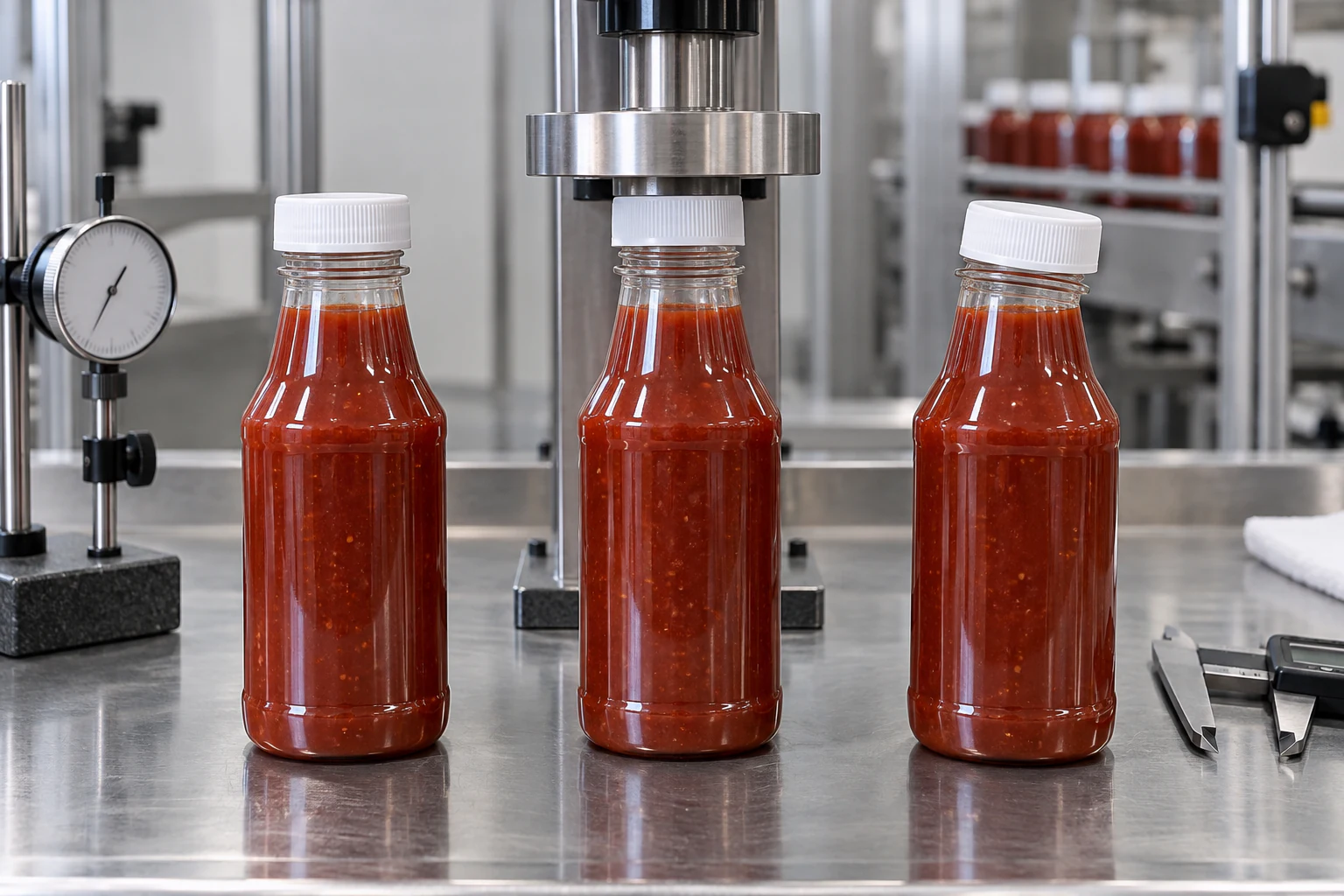
Decide whether the test ends at first yield, a specified displacement, a specified force or gross collapse. For capping-line work, a displacement-limited stop is often more informative than destroying every bottle because the usable package may be lost as soon as the neck or shoulder moves beyond the capper's alignment window. Photograph the failure before unloading and measure residual height after a defined recovery period.
| Test-Control Item | Record It As | Repeatability Risk If Omitted |
|---|---|---|
| Bottle condition | Empty, water-filled, sauce-filled, capped or uncapped | Internal support and closure compression change the curve |
| Temperature | Bottle wall temperature at test start | Warm polymer can yield at a substantially different load |
| Compression speed | mm/min or in/min | Rate-sensitive plastics can produce different peaks at different speeds |
| Platen and venting | Flat fixture, contact surface and vented/non-vented condition | Trapped air or local cap contact can add false support |
| Stop rule | Force, displacement, first peak or structural event | Different endpoints make lot comparisons invalid |
| Sample identity | Cavity, shift, time and production lot | Average values can hide one weak cavity or process drift |
Read the Force-Displacement Curve Before Looking at the Peak
A top-load curve usually begins with a seating region, followed by an approximately elastic rise. The slope over a defined part of that rise is apparent stiffness: k = change in force divided by change in displacement. A softer slope can reveal reduced wall support or process drift even when the bottle eventually reaches an acceptable maximum force.
The first sharp change in slope, first peak or sudden load drop marks a structural event. Stop the test or synchronize a camera at that point to determine whether the neck leaned, the shoulder inverted or the body wall folded. Without the failure image, two bottles with similar curves can be assigned the wrong root cause.
Peak force remains useful for comparing resin, weight and geometry, but a capping specification usually needs more than Pmax. Include force at the allowed displacement, displacement at the expected process load, first-yield behavior and residual deformation. Commercial top-load test systems use these same result families because production control depends on where deformation starts, not only on how much force finally crushes the container.
| Curve Region | Mechanical Interpretation | Possible Packaging Decision |
|---|---|---|
| Initial seating | Platen settles on the cap or finish and removes fixture clearance | Exclude inconsistent seating from stiffness calculations |
| Linear rise | Bottle structure carries load with mostly recoverable deformation | Compare stiffness by cavity, weight and conditioning state |
| Slope change | Local yielding begins before a dramatic collapse is visible | Inspect neck, shoulder and thin-wall zones immediately |
| First peak or load drop | Snap-through, buckle or finish movement has occurred | Use the failure location to direct mold or process correction |
| Post-yield region | Bottle carries load through a damaged geometry | Do not treat this reserve strength as usable capping capacity |
| Unloaded recovery | Elastic recovery versus permanent set | Reject structures that retain harmful height loss or neck tilt |
Neck Deflection: The Failure That Becomes a Crooked Cap
Neck deflection occurs when the finish translates, tilts or shortens under axial load. The weak zone may be the neck ring, the transition below the threads or one side of the shoulder. Even a small asymmetric movement can prevent the cap from entering the thread start squarely, creating a cocked cap, cross-threading or uneven liner compression.
The most useful measurements combine axial load with neck position. Record total bottle shortening, lateral finish movement and cap angle at the working load. A dial indicator, optical measurement or calibrated image can reveal tilt that a single force channel cannot. After unloading, recheck finish roundness, thread engagement and sealing-land orientation.
Common causes include off-center loading, uneven preform heating, asymmetric stretch and blow, thin material below the finish, excessive capper downforce or a shoulder geometry that transfers load through one narrow path. Improving only total bottle weight may miss the issue; material has to reach the structural load path.
| Observed Neck Symptom | Likely Check | Corrective Direction |
|---|---|---|
| Finish tilts toward one side | Platen alignment, mold cavity pattern and shoulder wall map | Correct loading alignment or rebalance the local material distribution |
| Finish moves down with little body damage | Neck-support ring and shoulder transition | Strengthen the load path directly below the finish |
| Cap starts crooked only on some cavities | Thread start, finish ovality, cavity identity and local neck stiffness | Separate cavity-level dimensional and compression data |
| Liner seals on one side only | Sealing-land angle after loading and applied cap torque | Reduce deflection before changing liner compression |
| Bottle recovers visually but leaks later | Residual neck angle, removal torque and side-storage leakage | Add post-load closure testing to the pass criteria |
Wall Buckling: Map the First Fold Back to Material Distribution
Wall buckling begins when a thin or unsupported zone can no longer carry the axial load transferred from the shoulder. The first fold often appears near a panel edge, grip feature, shoulder-body transition or heel. A final crushed bottle hides that origin, so the first-yield image is more valuable than a photograph taken after complete collapse.
Wall-thickness mapping should follow the failure path. Measure multiple heights and circumferential positions rather than reporting one average wall value. In stretch-blow-molded PET, axial stretch and radial expansion determine where material is distributed; in extrusion-blow-molded HDPE or LDPE, parison programming and mold draw shape the profile. The structural question is whether enough material reaches the zone carrying capper load without making the whole bottle unnecessarily heavy.
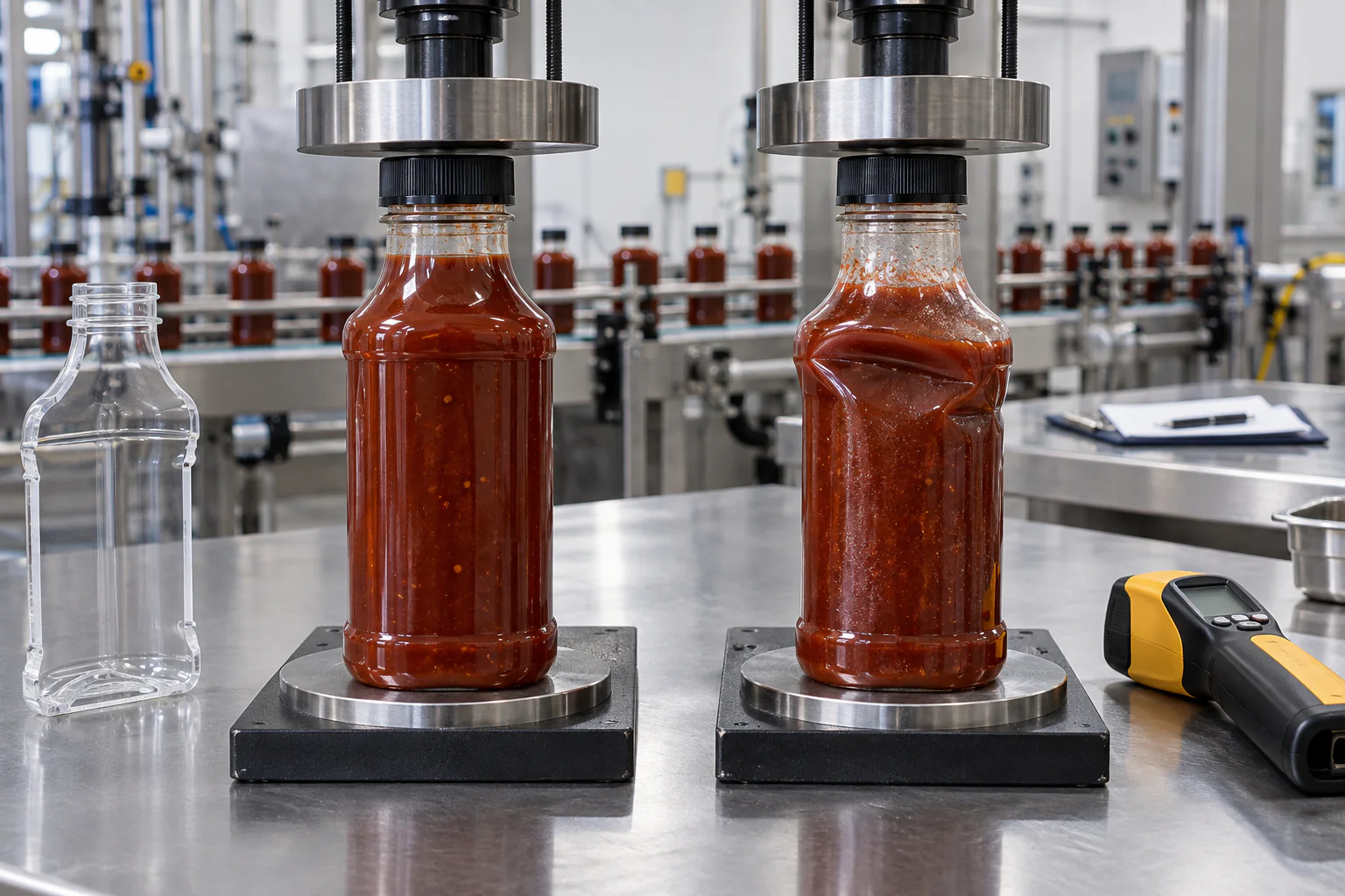
Ribs, panel boundaries and shoulder radii can redirect load, but geometry must remain compatible with squeezing and labeling. Clear PET squeeze bottles may need a stiffer capping load path while retaining controlled hand feel in the body. Squeezable BBQ sauce bottles can use more body flexibility, but the neck and shoulder still have to remain stable until the closure is seated.
Test Empty, Filled and Warm Bottles as Separate Conditions
Room-temperature empty-bottle data is a useful manufacturing baseline, but it may overstate the strength available on a warm filling line. Polymer stiffness changes with temperature, and a bottle capped soon after filling may still be carrying heat in the neck and shoulder. Record the wall temperature at the moment of compression rather than relying only on the filler set point.
Filled product can support the sidewall, while a closed cap and trapped headspace can change the apparent curve. A viscous sauce may also retain heat longer than water. For that reason, water-filled development samples are useful for early screening but do not fully represent a dense, hot or shear-thinning sauce under production timing.
Create separate acceptance groups for as-molded empty bottles, production-conditioned bottles at the capper, cooled filled packages and aged samples where creep or stress relaxation matters. Larger condiment squeeze bottles deserve additional attention because taller walls and greater filled mass can change the load path and handling after the cap is applied.
| Condition | Question It Answers | Do Not Substitute It For |
|---|---|---|
| Empty at controlled room temperature | Is the molded bottle structurally consistent by lot and cavity? | Warm-line or filled-package performance |
| Water-filled | How do fill mass and internal support change the baseline? | Actual sauce thermal and rheological behavior |
| Sauce-filled at capper temperature | Will the bottle resist the real downforce while process-conditioned? | Long-term cooled-package behavior |
| Cooled and capped | Did loading or cooling leave neck, torque or leakage damage? | High-temperature capping response |
| Aged or temperature-cycled | Do creep, relaxation or residual stress change the result? | Immediate production control |
Set Acceptance Limits from the Process Window, Not a Generic Force Table
Published force ranges can help size test equipment, but they are not acceptance standards for a specific sauce bottle. A 20 g bottle with a wide shoulder and a 20 g bottle with a narrow waist can fail at different loads and in different locations. Test speed, cap presence, temperature and allowed displacement can shift the reported result again.
Begin by measuring or obtaining the maximum downward load applied by the intended capper under normal and upset conditions. Run line trials to identify the highest load that still produces correct cap seating, then compare that process requirement with the bottle's lower-tail test behavior under the worst qualified temperature and fill condition. If an engineering safety margin is applied, document why it is appropriate for that capper, bottle and process instead of borrowing a universal multiplier.
A useful specification combines several limits: minimum force at an allowed displacement, maximum deflection at working load, no first yield below the protected process level, no harmful permanent set, and no closure defect after loading. The cap and closure system should remain part of the validation because a structurally acceptable bottle still fails the package if torque, liner compression or sealing changes after the top-load event.
| Acceptance Element | Example Specification Form | Reason |
|---|---|---|
| Working-load deflection | At process load Fwork, axial displacement must not exceed the approved limit | Protects capper height and finish alignment |
| First-yield floor | No curve discontinuity or visible buckle below the protected load | Prevents hidden structural damage before cap seating |
| Residual deformation | Height loss and neck angle after unloading remain within drawing or line limits | Catches permanent set that peak force misses |
| Closure outcome | No cocked cap, thread damage, torque failure or leakage after loading | Connects compression data to finished-package function |
| Statistical lot rule | Defined sample count, acceptance number and treatment of cavity outliers | Prevents a strong average from hiding a weak production stream |
Sampling by Mold Cavity, Shift and Process Condition
Top-load data becomes useful for quality control only when the sample plan can locate variation. Pulling several bottles from one carton and reporting an average may miss a weak cavity, a heater-zone change or a short period of unstable wall distribution. Identify cavity where the mold permits it and spread samples across startup, steady production and the end of the run.
Report individual values, mean, range and the failure mode for every specimen. Standard deviation can describe spread, but do not let it erase a different failure mechanism. A low result caused by neck tilt belongs to a different corrective path from a low result caused by a body-panel fold, even when both fall below the same force limit.
When a lot fails, quarantine by traceable process boundaries and repeat the measurement after checking bottle weight, critical neck dimensions, wall distribution and conditioning. A re-test without a documented assignable cause can turn a real manufacturing drift into an apparently passing average.
| Sampling Dimension | Why It Is Separated | Useful Record |
|---|---|---|
| Mold cavity | One cavity may carry different wall or finish behavior | Individual curve, bottle weight and failure location |
| Production time | Heating, resin drying and process balance can drift | Startup, mid-run and end-run samples |
| Temperature condition | Warm and room-temperature strength are not interchangeable | Actual bottle wall temperature at test |
| Capper head or lane | A machine-side issue can resemble a bottle defect | Head number, applied load/torque and cap outcome |
| Production lot | Creates a repeat-order comparison baseline | Lot code, resin batch, approved limits and retained samples |
Gracepack Bottle and Cap Qualification for High-Speed Lines
Gracepack coordinates the bottle body, neck finish and closure as one mechanical system. Our manufacturing base includes injection molding for caps and preforms, blow molding for bottle bodies, more than 500 owned molds and more than 5,000 standard bottle designs. That range allows an existing shoulder, finish or gram-weight route to be compared before a custom mold is justified.
The qualification work begins with the bottle drawing, target resin and weight, wall map, finish dimensions, cap drawing, liner or valve, fill temperature and capper settings. Samples can then be grouped by cavity and condition for compression testing, followed by actual cap application, torque and leakage checks. We do not replace a customer's line-specific acceptance limit with a generic catalog number; the limit is built around the package and the production condition it must survive.
Food-contact reports and ISO 22000 system documentation can be matched to the selected material route, but those documents do not prove mechanical top-load performance. Mechanical approval comes from controlled measurements, representative production samples and confirmation on the intended filling and capping equipment.
| Qualification Input | Gracepack Review | Result for the Line Trial |
|---|---|---|
| Bottle drawing and reference sample | Finish, shoulder, body, base and target load path | Critical measurement plan |
| Resin, gram weight and process | Preform or parison route and wall-distribution risks | Sample variants worth testing |
| Cap, liner or valve | Thread fit, compression stack and capping interface | Matched bottle-and-cap sample set |
| Fill and capper conditions | Temperature, timing, downforce, torque and line speed | Conditioned top-load and line-trial matrix |
| Production traceability | Cavity, lot and retained sample structure | Repeat-order QC reference |
FAQ About Sauce Bottle Top-Load Testing
What is top-load testing for a plastic sauce bottle?
It is an axial compression test that records how much force a bottle carries and how far it deforms. Useful outputs include crushing yield load, deflection at yield, maximum load, stiffness, failure location and permanent set.
What top-load force should a sauce bottle pass?
There is no universal force for all sauce bottles. The limit must reflect bottle size, geometry, material, gram weight, temperature, fill condition, capper downforce, test speed and the maximum displacement the line can tolerate.
Should top-load testing use empty or filled bottles?
Test both when the bottle will run on an automated sauce line, but report them as separate conditions. Empty bottles show manufacturing consistency; filled and warm bottles show how the package behaves during the real process.
Why can a bottle pass peak force but still fail capping?
The neck or shoulder may deflect before the maximum force is reached. That early movement can create a cocked cap, cross-threading or poor liner compression even though the body later carries a higher load.
How many bottles are needed for a top-load test?
The sample count should be defined by the project specification and production risk. It should cover relevant mold cavities, production times, temperature conditions and any capper heads associated with failures rather than relying on one convenient carton sample.
Can food-contact certification prove top-load strength?
No. Food-contact documentation addresses material suitability within its stated scope. Top-load strength is a mechanical property that must be verified on the actual bottle under controlled and process-representative conditions.
Request a Sauce Bottle Top-Load Sample Review
Send the bottle drawing or physical reference, resin, target gram weight, capacity, neck finish, cap and liner, fill temperature, capping timing, measured or specified capper downforce, line speed and current failure photos. Gracepack can compare suitable existing mold routes and prepare a sample plan around the weak zone rather than changing the entire bottle blindly.
The review can include a dimension checklist, wall-thickness measurement map, empty and process-conditioned test matrix, matched bottle-and-cap samples and line-trial checkpoints for neck angle, applied torque, removal torque and leakage.


